Unlike regular buttons that only need level detection to identify triggers, we need to measure the signal values of the XY axis joystick sensor, so we need to use an Analog-to-Digital Converter (ADC).
By the way, the XY axis joystick sensor looks like this - it’s the same joystick used in remote controllers for children’s toy cars.
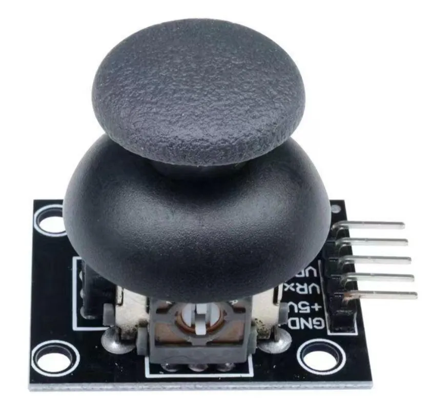
It has 5 pins: GND, VCC, VRx, VRy, and SW.
Among them, VRx and VRy are two analog input pins used to measure the X and Y axis signals of the joystick.
SW is a button pin used to detect the joystick button press.
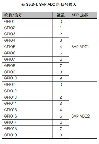
ESP32-S3 integrates two 12-bit SAR ADCs, supporting both single conversion results and continuous conversion results. However, not all GPIO pins support ADC conversion. According to the technical reference manual, the distribution is as follows:
Dependencies:
[dependencies]
esp-hal = { version = "~1.0", features = [ "esp32s3","unstable","defmt"] }
anyhow      = {version = "=1.0.102", default-features = false}
esp-bootloader-esp-idf = { version = "0.4.0", features = ["esp32s3"] }
critical-section = "1.2.0"
esp-alloc        = "0.9.0"
rtt-target       = "0.6.2"
defmt = "1.0.1"
defmt-rtt = "1.1.0"
nb = "1.1.0"
Reading XY Axis Values
The esp_hal ADC functionality is in the analog module.
First, initialize the GPIO pins:
    let cpu_clock = hal::clock::CpuClock::max();
    let config = hal::Config::default().with_cpu_clock(cpu_clock);
    let peripherals = hal::init(config);
I connected the X and Y axis pins to GPIO1 and GPIO2. From the image above, we can see that GPIO1 and GPIO2 belong to the ADC1 module.
    let mut adc1_config = AdcConfig::new();
    let mut x_adc = adc1_config.enable_pin(peripherals.GPIO1, Attenuation::_11dB);
    let mut y_adc = adc1_config.enable_pin(peripherals.GPIO2, Attenuation::_11dB);
    let mut adc1 = Adc::new(peripherals.ADC1, adc1_config);
The Attenuation::_11dB setting comes from the official technical manual: https://documentation.espressif.com/esp32-s3_technical_reference_manual_cn.pdf
Chapter 39 mentions that attenuation can be configured to 0 dB, 2.5 dB, 6 dB, and 12 dB. In the Rust implementation, it’s actually 0 dB, 2.5 dB, 6 dB, and 11 dB.
Then read the data in a loop:
loop {
        // Read X axis ADC value
        let x_value: u16 = nb::block!(adc1.read_oneshot(&mut x_adc)).unwrap();
        // Read Y axis ADC value
        let y_value: u16 = nb::block!(adc1.read_oneshot(&mut y_adc)).unwrap();

        // ADC value range: 0-4095 (12-bit ADC)
        // Midpoint value is approximately 2048 (joystick centered)
        println!("X: {}, Y: {}", x_value, y_value);

        delay.delay_millis(100);
    }
After flashing the firmware, we can see the X and Y values in the console. By moving the joystick, we can see the X and Y values changing continuously.
Z Axis Detection
The Z axis is essentially a button mounted on the joystick. It follows the normal button handling process: using GPIO interrupts to determine if the button is pressed.
First, define a static variable to save the button state:
static Z_BUTTON: Mutex<RefCell<Option<Input>>> = Mutex::new(RefCell::new(None));Set up the interrupt handler:
    let mut io = Io::new(peripherals.IO_MUX);
    io.set_interrupt_handler(button_handler);
SW is connected to pin 35, we also need to set up listening for falling edge triggered interrupts:
  let z_pin = peripherals.GPIO35;
    let config = InputConfig::default().with_pull(Pull::Up);
    let mut z_button = Input::new(z_pin, config);

    critical_section::with(|cs| {
        z_button.listen(esp_hal::gpio::Event::FallingEdge);
        Z_BUTTON.borrow_ref_mut(cs).replace(z_button);
    });
Implement the button_handler callback as follows:
#[handler]
#[ram]
fn button_handler() {
    critical_section::with(|cs| {
        let mut z_btn = Z_BUTTON.borrow_ref_mut(cs);
        if let Some(ref mut btn) = *z_btn {
            if btn.is_interrupt_set() {
                println!("Button pressed!");
                btn.clear_interrupt();
            }
        }
    });
}